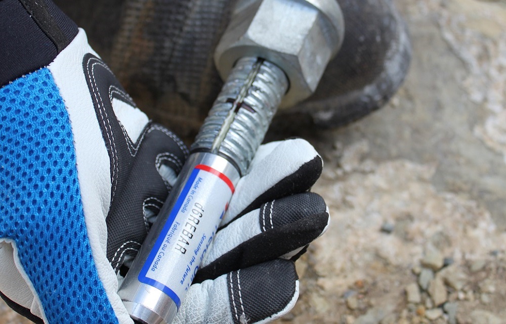
YieldPoint’s d-Rebar measures how the strain or load develops along rigid bolts, such as resin rebar, and hence to assess the Factor of Safety against steel rupture. The technology is applicable to rebar elements, threaded bolts, and a variety of other steel elements used in mining, civil and construction projects. It has the potential to predict the risk of catastrophic structural failure: in fact the d-Rebar data can enhance many aspects of engineering design.
The physical instrumentation of the d-Rebar is recessed into a 3.2mm wide groove which is milled into the steel bolt. Typically the instrumentation consists of up to six (6) axially configured long base-length strain gauges (300-600mm baselength). The strain gauges are encapsulated within an epoxy resin and are designed to withstand the rigors of bolt installation using standard procedure.
Technology:
YieldPoint’s d-Rebar measures how the strain or load develops along rigid bolts, such as resin rebar, and hence to assess the Factor of Safety against steel rupture. The technology is applicable to rebar elements, threaded bolts, and a variety of other steel elements used in mining, civil and construction projects. It has the potential to predict the risk of catastrophic structural failure: in fact the d-Rebar data can enhance many aspects of engineering design.
The physical instrumentation of the d-Rebar is recessed into a 3.2mm wide groove which is milled into the steel bolt. Typically the instrumentation consists of up to six (6) axially configured long base-length strain gauges (300-600mm baselength). The strain gauges are encapsulated within an epoxy resin and are designed to withstand the rigors of bolt installation using standard procedure.
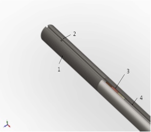
Fig 1. Both ends of the inductive strain gauge are positioned within the 3.2mm groove.
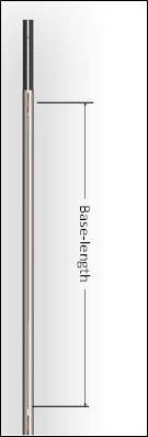
Fig 2: The baselength (BL) is the distance between the ends of the gauge which are attached to the rebar using micro-drilled holes.
Configuration:
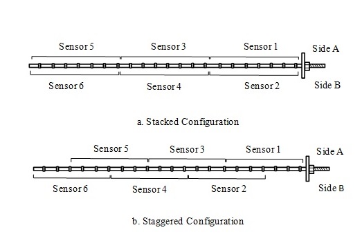
Fig 3: Staggered versus stacked configuration
d-Rebar technology can be applied to any rigid bolt or bar. Either a pair of strain gauges (for end anchored bolts spun in resin) or an array of strain gauges can be specified. For applications which require enhanced axial load resolution the strain gauge array should be staggered (Fig3 upper). If bending moments need to be more accurately resolved then a stacked configuration may be preferable (Fig 3. lower). A theoretical comparison of both is presented in a related technical note.
The specification of the strain gauge locations should be based on an understanding of the load distribution along a fully grouted rock bolt. At the collar of the borehole the load depends on the stiffness (i.e. bearing conditions) of the faceplate. Along the length of the bolt the load increases in the bolt along the “pick-up” length and reaches a peak at the neutral point. The load decreases along the remainder of the bolt length, the “anchor length”, and is zero at the free end. In the case of a stiff bearing surface for the plate and a rapid decrease in the displacement magnitude around the excavation then the neutral point may actually occur at the faceplate.
Individual Calibration:
Every instrument is subjected to a multipoint calibration. The calibration coefficients are written into microcontroller memory, and a piecewise linear function is used to enhance linearity the output signal and applied strain.
Installation:
The d-Rebar has been specifically designed to be spun in epoxy resin using a rock drill. The electronics head can be either (i) detachable from the bolt during installation or (ii) attached to the end of the bolt so that the hole assembly is encapsulated. The first option results in an easier installation procedure but care must be taken to properly seal the end connector in wet conditions.
Installation Precautions:
Installing instrumentation with a rock drill can be challenging even for the toughest product. Care must be taken to ensure that the drill is well aligned with the borehole.
Features:
- Instrumented rebar that can be spun in resin
Available with 2 to 6 strain gauges in two diametrically opposed slotted channels. - Readout head encapsulated in stainless steel tube for protection.
- Microcontroller provides output directly in m
- Each bolt is individually calibrated.
- Immunity to hostile environment
- High survivability to shock and vibration
- Easy to install and maintain
- Low cost peripheral devices for data-logging (d-Logger,BluLink or BluLogger) and data upload using LTE-M. Wifi, or Ethernet (BluGateway)
- Wireless mesh using 900MHz 1for1 radio.
Manual readout:
Data download using YieldPoint’s low cost d-Reader readout unit or any Android device using the BluPoint product-line. Both provide the temperature and displacement data directly in °C and mm.
Data-logging:
Data from the d-Rebar can be collected using YieldPoint’s d-Logger dataloggers (d1Logger and d4Logger). The BluLink and BluLogger and BluGateway also provide datalogging and Bluetooth 5 download.
Automated data retrieval:
Clusters of instruments (4 per Logger) that are monitored using YieldPoint’s d4Logger can be wireless networked using:
- 1for1 radios: a 900MHz wireless mesh solution.
- BluGateWay if either a WiFi, LTE-M or Ethernet network is available.
Case Study 1: Monitoring Rock Bolt Loads at an Intersection
As part of the SIUC project outlined above a number of intersections were also monitored. In one particular intersection the bolt were loaded minimally in the 3 months following excavation. However on July 10 th a dramatic increase in microstrain was detected for most bolts ia the intersection. The occurence of the unexpected movement was recorded by a d4logger. Some bolts loaed up most close to the head, others in the middle of the bolt and some towards the toe. Only when the distribution of strain and displacement were contoured across the array could the existence of an inclined structure be inferred. The displacement plot suggests that an interaction of this incled structure with a “cutter” observed in the haunch defined a wedge than needed to be supported by the bolt array.
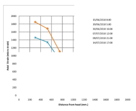
Temporal plot of bolt and spatial plot for bolt 100555074
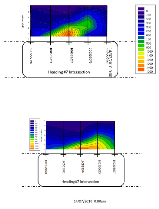
Strain in microstrain (Top) and Disp in microns (Bottom) measured by d-Rebar
Case Study 2: Monitoring rock bolt loading at mid-pillar
YieldPoint worked with reasearchers at Southern Illinois University at Carbondale (Prof. Sam Spearing) and NIOSH ( a branch of the CDC (US Center for Disease Control) to develop an innovative instrumented rebar. This technology based on “long baselength” strain gauges was used to monitor bolt loads at several US coal mines operated by Peabody Energy. The minining involved “the room and pillar” mining method. Full results of the study were published in a paper in the IJRMMS. Data were continuously monitored using the d4Logger.
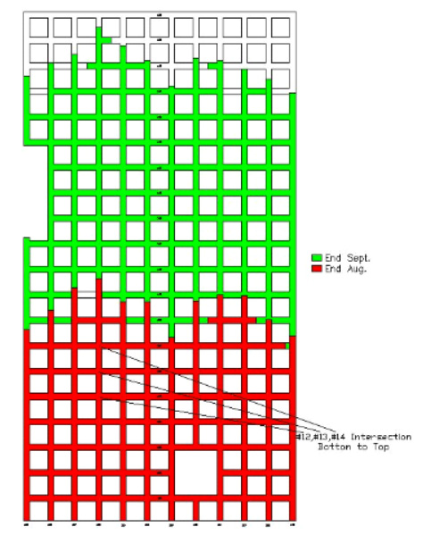
The mining sequence.
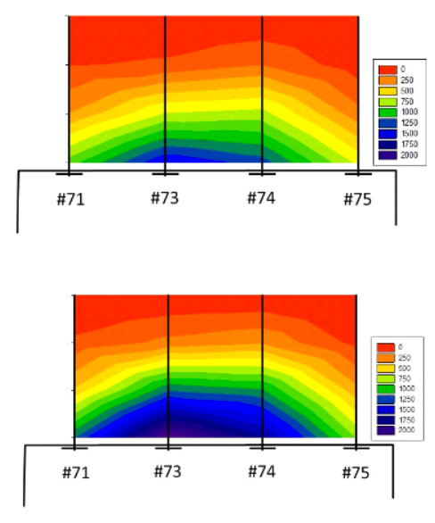
Displacement measured by d-Rebar in microns

